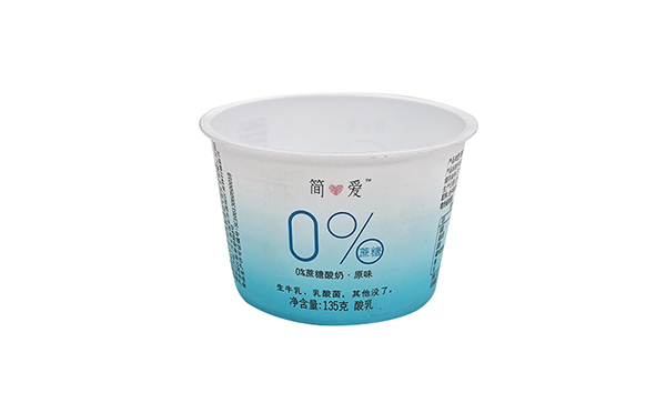
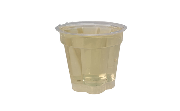
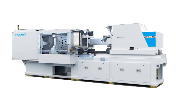
The Real-E 280 is one of the Real P series of fully electric injection molding machines designed and manufacturered by Valmo Injection Equipment Co., ltd. for medical parts precise injection molding production and thin-wall packaging production. It's now one of the fast developing full electric injection molding machine providing the the thin-wall containers injection molding solutions to package producers around the world.
| PARAMETER | UNIT | Real-E 280 | |||||||||||||||
|---|---|---|---|---|---|---|---|---|---|---|---|---|---|---|---|---|---|
| INJECTION UNIT | 630h | 1000h | 1400h | ||||||||||||||
| A | B | C | A | B | C | A | B | C | |||||||||
| Screw diameter | mm | 40 | 45 | 50 | 45 | 50 | 60 | 50 | 60 | 70 | |||||||
| Injection pressure | bar | 2450 | 1950 | 1600 | 2600 | 2100 | 1460 | 2450 | 1950 | 1450 | |||||||
| Injection Speed | mm/s | 300 | 300 | 300 | |||||||||||||
| Injection Rate | cc/s | 376 | 476 | 588 | 476 | 588 | 847 | 588 | 847 | 1155 | |||||||
| CLAMPING UNIT | |||||||||||||||||
| Clamping force | kN | 2800 | |||||||||||||||
| Clamping Stroke | mm | 570 | |||||||||||||||
| Dist. between tie bars (HxV) | mm | 720 x 720 | |||||||||||||||
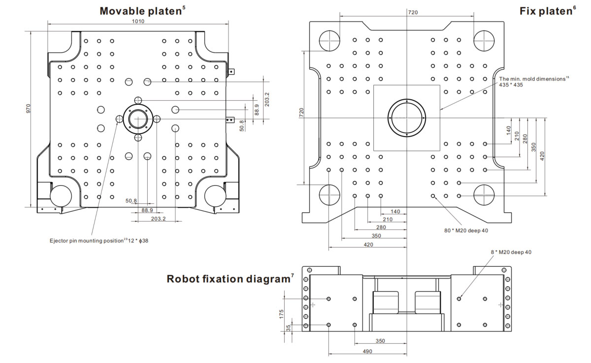
Real-E 280 Mold Platen Diagram
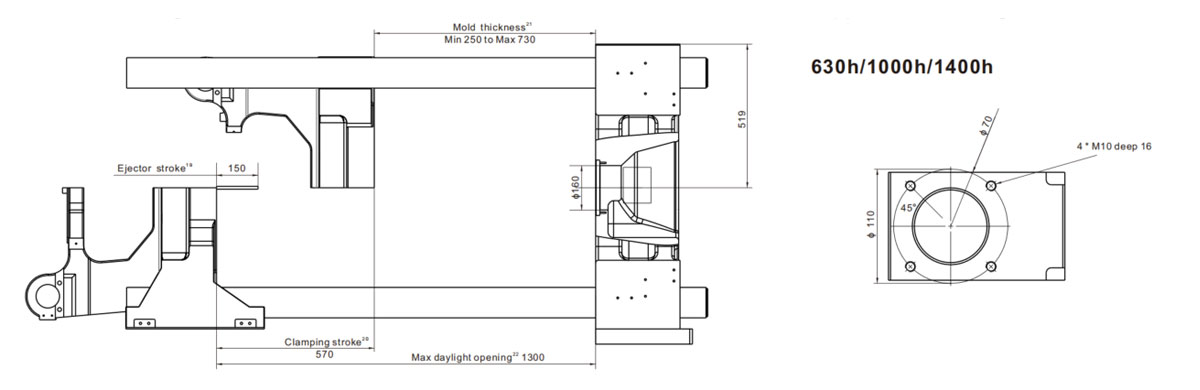
Real-E 280 Mold Area Diagram
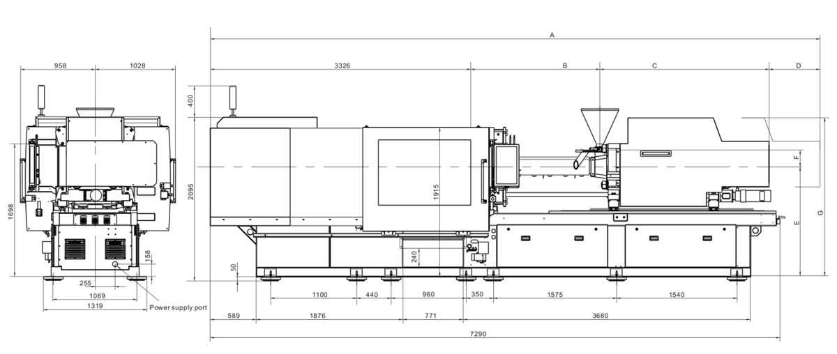
Real-E 280 Dimensional Diagram
| Real-E 280 | |||||||
|---|---|---|---|---|---|---|---|
| A | B | C | D | E | F | G | |
| 630h | 6656 | 1255 | 1625 | 450 | 1410 | 230 | 1965 |
| 1000h | 7357 | 1526 | 2055 | 450 | 1410 | 244 | 2038 |
| 1400h | 7650 | 1660 | 2165 | 500 | 1410 | 244 | 2038 |
The injection-compression function of Valmo full electric injection molding machien is a combination of both injection molding and compression molding. The melt plastic injected into mold while mold still open and subsequently distributed evenly throughout the cavity after clamping unit compressed. The injection-compression function benefits included shorten cycle time, decreased warping in the mold part, higher dimensional accuracy of parts, higher efficiency and reduce costs. The advanced Valmo VICO control system make it possible to reduce wall thickness, reduce parts weight.
Beverage closures production require a long-term stable and high-speed production, and excellent production cost control.
High speed injection molding system and high-performance clamping mechanism design provides a very short cycle time. The mould precision
grade template parallelism and compact solid frame structure effectively reduce the mechanical and mold consumption. The special injection
structure design and high speed plasticizing screws makes the injection rate faster. Flexible programmablel function optimized the production
process to achieve the shortest cycle time.
In addition to integrate a number of auxiliary functions, such as automatic feeding, 96 district hot runner controller, etc., more dash forward
show excellent cost performance.
Thanks to the excellence of the motion control technology and top grade servo drive system, injection precision reach to 0.01mm, injection weight
offset less then 0.01g. Very suitable for miniaturization of advanced production with high precision and reliability requirements.
Carrying ultra-high dynamic servo system, injection speed up to 1000mm/s. Can satisfy the complex geometric shaps, optical len and thin electronic
parts.
VICO control system can programming any special process of complex requirements, greatly reduce the development time of new products and cost.
Multi-Injection system can be adapted to existing mold technology and infrastructure.
Through mixes use of different type of second unit can be achieved multi-color injection process.
Step 1:Injection of component 1, and move core side to cavity 2 → Step 2 Injection of component 2
Step 1Innjection of component 1 → Step 2 Lifting index platen, turning 180 degree → Step 3 Pull-back of index platen → Step 4 Injection of component 2, Simultaneous injection of the next substrate.
The mold usually remains closed for this operation, and mold is compact and inexpensive
Step 1 Injection of component 1 → Step 2 Pull-back the slide → Step 3 Injection of component 2
The number of rotation could up to 4, and this is the most widely used multi-component process
Step 1 Injection of component 1 → Step 2 Rotation the mold → Step 3 Injection of component 2 Simulataneous injection of component 1