
sales06@switek.biz

+86 186 5927 5869

Subscript to Us
sales06@switek.biz
+86 186 5927 5869
Subscript to Us
Keywords:Panasonic A6 Servo Motor, Panasonic A6 Servo Motor Driver, Panasonic A6 Servo Motor setting instruction
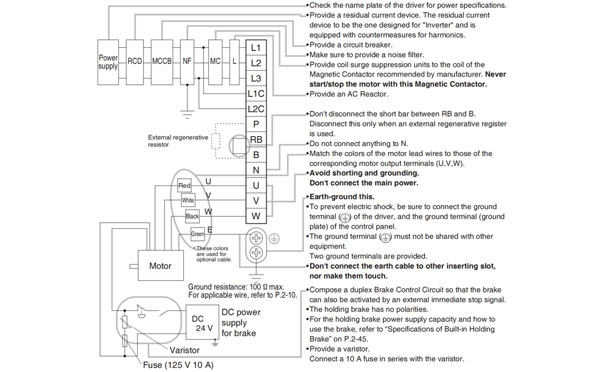
The correct wiring is the guarantee of safety of the Panasonic A6 series AC servo motor application, here in this chapter we'll introduce the correct wiring of the Panasonic A6 AC servo motor and driver in your machineries and automation system.
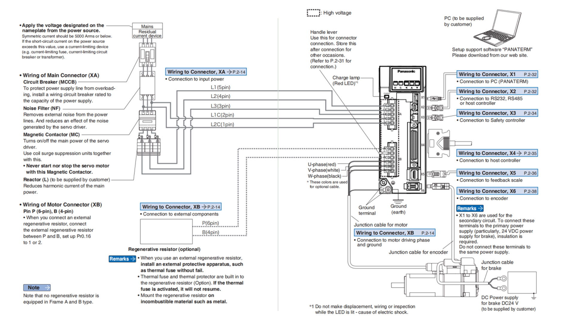
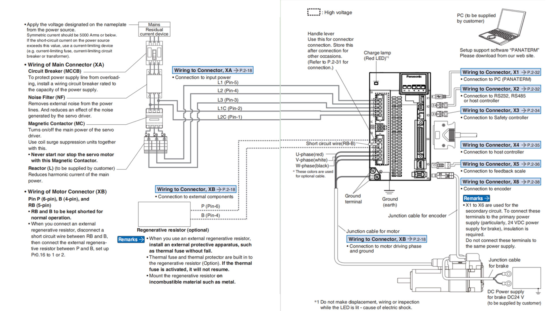
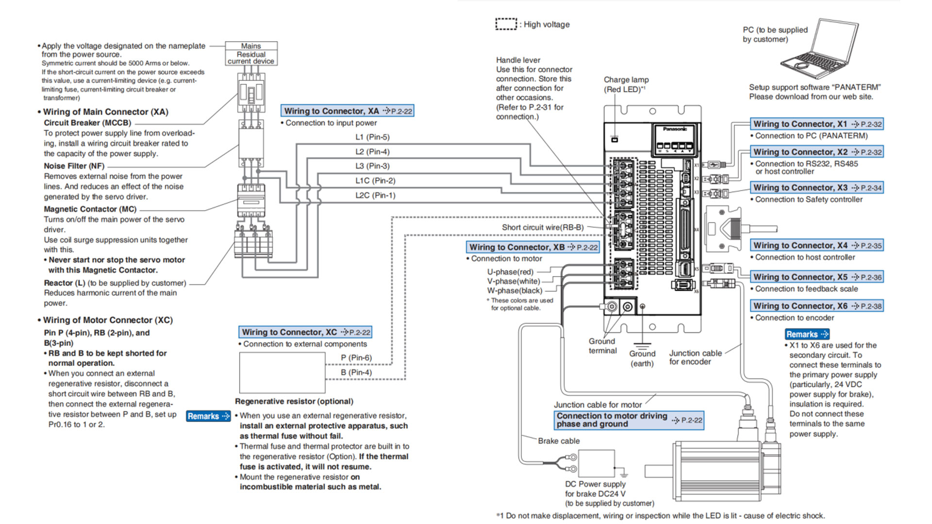
Related page → •P.2-14 "Wiring of the Main Circuit (A to B-frame, 100 V/200 V type)" •P.2-28 "Specifications of Motor connector"
Note → The wiring indicated with the broken line shall be provided only when required.
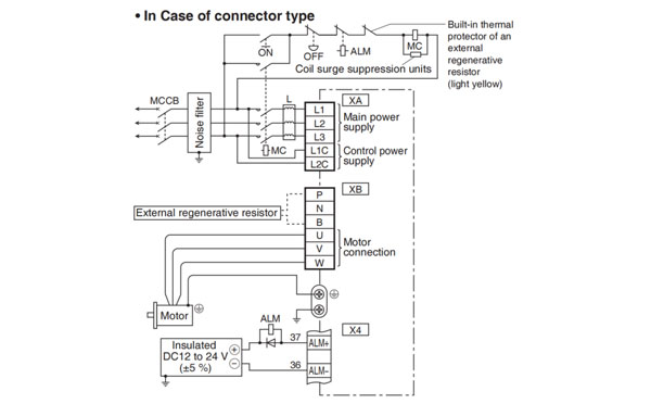
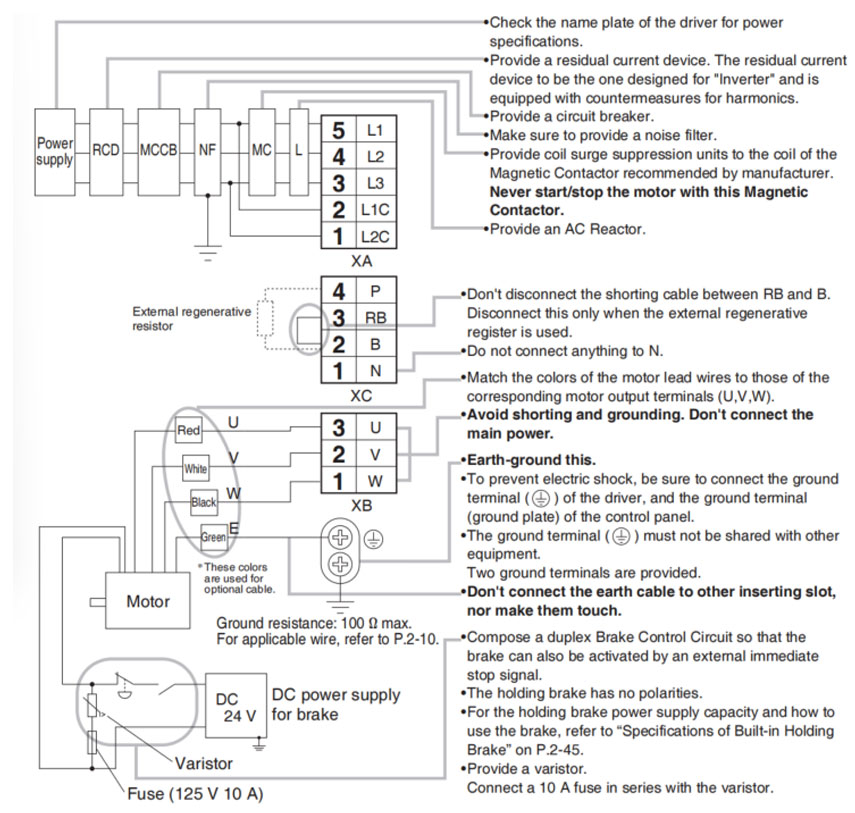
Related page → •P. 2-28 "Specifications of Motor connector" •P.2-31 "Wiring method to connector" •P.7-132 "Connector kit fo XA" •P.7-133 "Connector kit for XB"
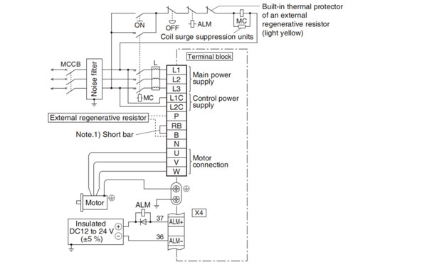
Compose the circuit so that the main circuit power will be shut off when an error occurs. However, if you want to use "immediate stop function" and the main circuit power turns off, please be aware that you will no longer be able to use "immediate stop function".
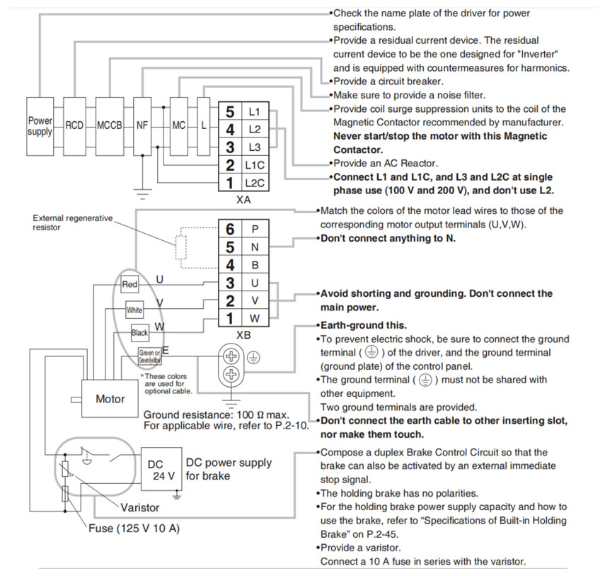
Power supply Single phase, 100 V - 15% to 120 V +10%/200V - 15% to 240V + 10%
Power supply 3-phase, 200 V - 15% to 240V + 10%
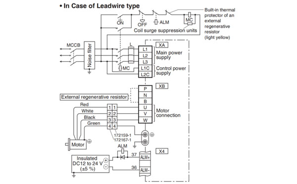
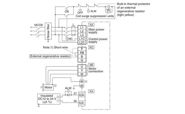
Note.1)
| Frame No. | Short wire (Accessory) | Built-in regenerative resistor | Connection of the connector XB | |
| In case of using an external regenerative resistor. | In case of not using an external regenerative resistor. | |||
| A-frame B-frame | without | without | • Connect an external regenerative resistor between P-B | •Always open between P-B |
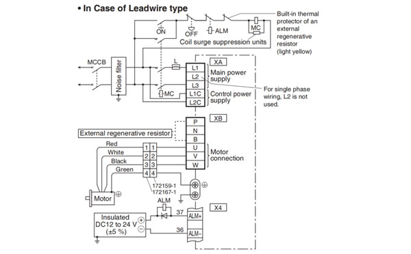
Note → The wiring indicated with the broken line whall be provided only when required.
Related page → •P.2-28 "Specifications of Motor connector" •P.2-31 "Wiring method to connector"
Note → This overall wiring diagram is a typical one. The pages that follow show wiring for specific application. The wiring indicated with the broken line shall be provided only when required.
Related page → •P.7-108 ..."Options" •P.2-18 "Wiring of the Main Circuit (A to B-frame, 100 V/200 V type)" •P. 2-28 " Specifications of Motor connector"
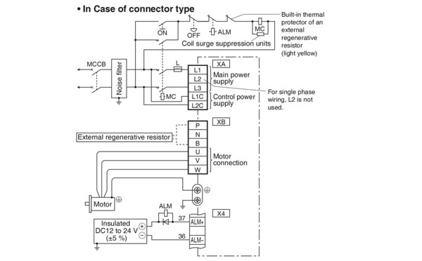
Note → The wiring indicated with the broken line shall be provided only when required.
Related page → •P.2-28 "Specifications of Motor connector" •P.2-31 "Wiring method to connector" •P.7-132 "Connector kit for XA" •P.7-133 "Connector kit for XB"
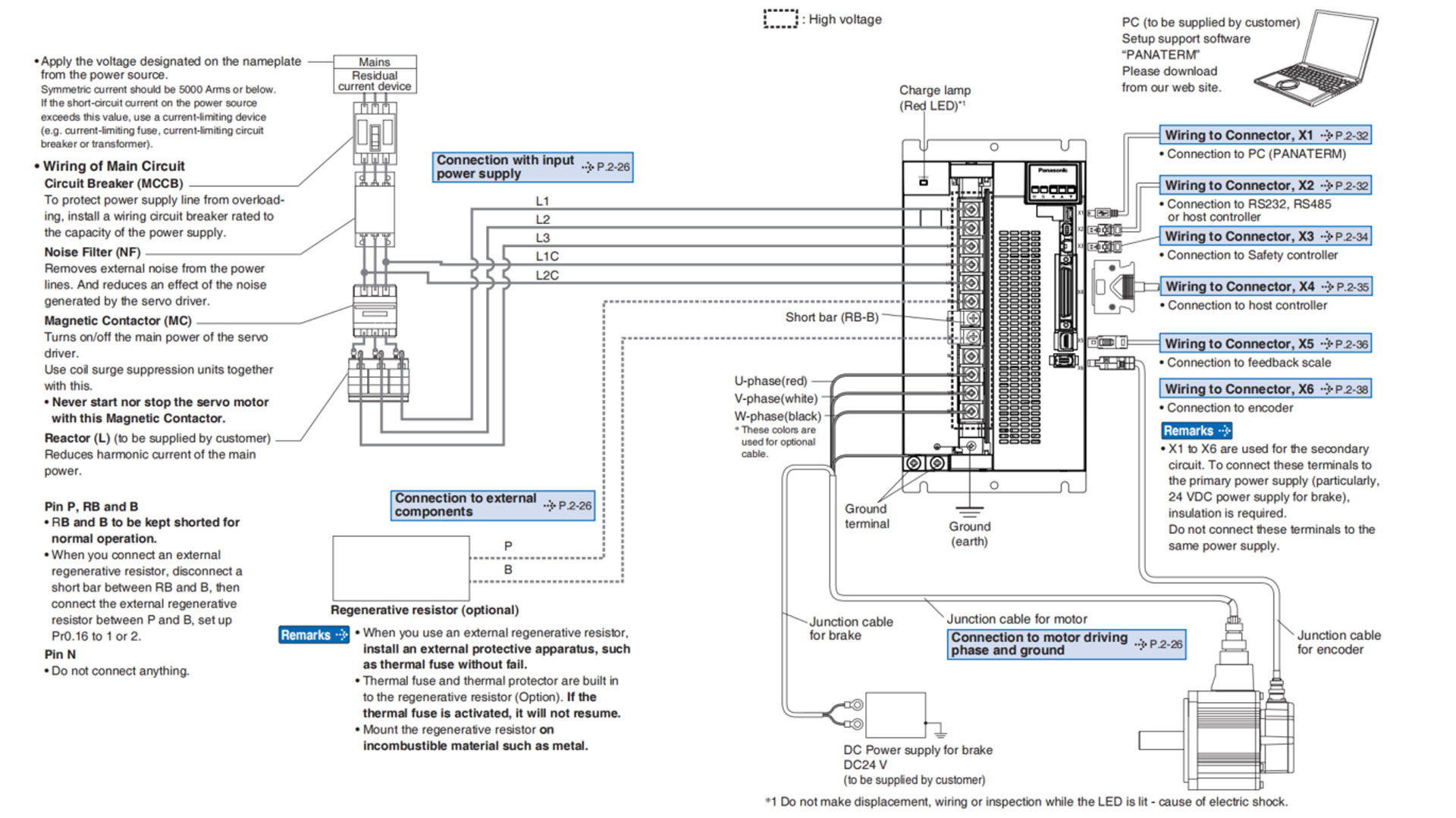
Note → This overall wiring diagram is a typical one. The pages that follow show wiring for specific application. The wiring indicated with the broken line shall be provided only when required.
Related page → •P.7-108... "Options" •P.2-18 "Wiring of the Main Circuit (E-frame, 200V type)" •P.2-28 "Specifications of Motor connector"
Note → The wiring indicated with the broken line shall be provided only when required.
Related page → •P.2-28 "Specifications of Motor connector" •P.2-31 "Wiring method to connector" •P.7-132 "Connector kit for XA, XC" •P.7-133 "Connector kit for XB"
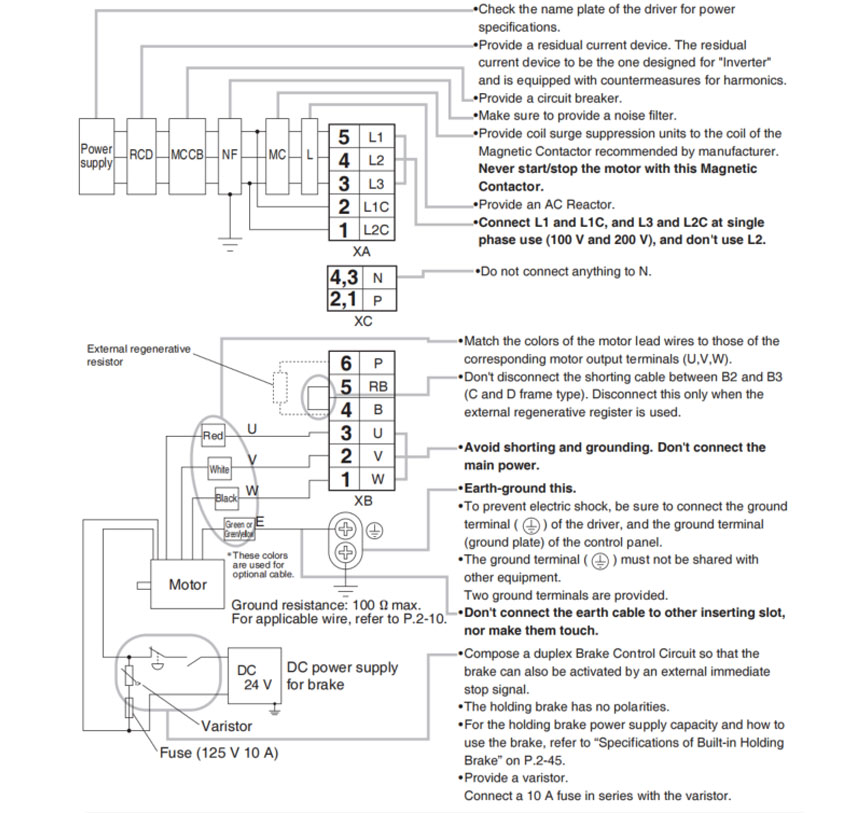
Compose the circuit so that the main circuit power will be shut off when an error occurs. However, if you want to us "immediate stop function" and the main circuit power turns off, please be aware that you will no longer be able tous "immediate stop function".
Power supply 3-phase, 200V -15 % to 240V +10%
Note.1)
| Frame No. | Short wire (Accessory) | Built-in regenerative resistor | Connection of the connector XC | |
| In case of using an external regenerative resistor. | In case of not using an external regenerative resistor. | |||
| E-frame | with | with |
|
|
Note → The wiring indicated with the broken line shall be provided only when required.
Relalted page → &bullP.2-28 "Specifications of Motor connector" •P.2-31 "Wiring method to connector"
Note → This overall wiring diagrma is a typeical one. The pages that follow show wiring for specific application. The wiring indicated with the broken line shall be provided only when required.
Related page → •P.7-108... "Options" •P.2-26 "Wiring of the Main Circuit (F-frame, 200 V type)" •P.2-28 "Specifications of Motor connector"
Note → The wiring indicated with the broken line shall be provided only when required.
Related page → •P.2-28 "Specifications of Motor connector"
Compose the circuit so that the main circuit power will be shut off when an error occurs. However, if you want to use "immediate stop function" andd the main circuit power turns off, please be aware that you will no longer be able to use "immediate stop function".
Power supply 3-phase, 200 V -15% to 230 V +10%
Note.1)
| Frame No. | Short bar (Accessory) | Built-in regenerative resistor | Connection of terminal block | |
| In case of using an external regenerative resistor. | In case of not using an external regenerative resistor. | |||
| F-frame | with | with |
|
|
Note → The wiring indicated with the broken line shall be provided only when required.
Related page → •P.2-28 "Specifications of Motor connector"


