


Keywords:Panasonic A6 Servo Installation Instruction, Panasonic A6 Driver, Panasonic A6 Series Servo Motor Manual
Here in this chapter is the definition of the pins for the input signal to communicate with the Panasonic A6 series of Motor and Driver.
You can select appropriate interface out of two kinds, depending on the command pulse specifications.
| Pin No. | 44 45 | Title of signal | Command pulse input 1 | Related control mode | P | S | T | F |
| Symbol | Pin No.44:PULSH1 Pin No.45: PULSH2 | I/F circuit | P.3-34 | |||||
| Pin No. | 46 47 | Title of signal | Command pulse sign input 1 | Related control mode | P | S | T | F |
| Symbol | Pin No. 46: SIGNH1 Pin No.47: SIGNH2 | I/F circuit | P.3-34 | |||||
| ||||||||
| Pin No. | 1 3 4 | Title of signal | Command pulse input 2 | Related control mode | P | S | T | F |
| Symbol | Pin No.2: OPC2 Pin No.5: SIGN1 Pin No.6: SIGN2 | I/F circuit | P.3-33 | |||||
| Pin No. | 2 5 6 | Title of signal | Command pulse sign input 2 | Related control mode | P | S | T | F |
| Symbol | Pin No.2: OPC2 Pin No.5: SIGN1 Pin No.6: SIGN2 | I/F circuit | P.3-33 | |||||
| ||||||||
•P.3-33 "Inputs and outputs on connector X4" •P.4-10 "Details of parameter"
• Input format command pulse
| Pr0.06 setup value (Command pulse rotational direction setup) | Pr0.07 setup value (Command pulse input mode setup) | Command pulse format | Signal title | Positive direction command | Negative direction command |
|---|---|---|---|---|---|
| 0 | 0 or 2 | 90° phase difference 2-phase pulse (A+B-phase) | PULS SIGN | 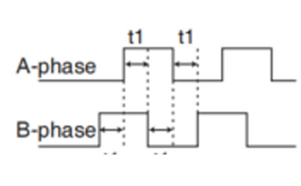 B-phase advances to A by 90°. | 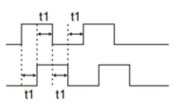 B-phase delays to A by 90°. |
| 1 | Positive direction pulse train + Negative direction pulse train | PULS SIGN | 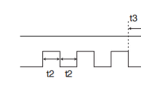 | 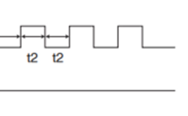 | |
| 3 | Pulse train + Signal | PULS SIGN | 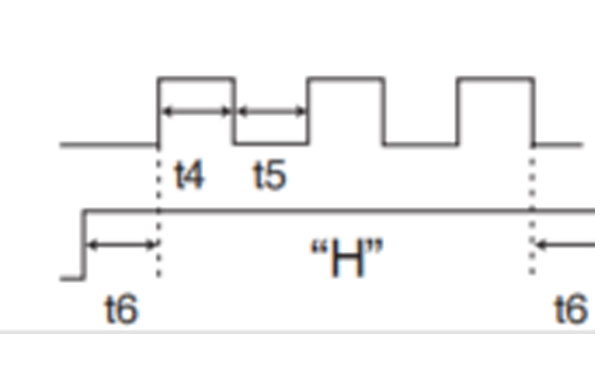 | 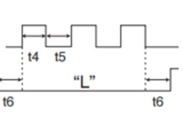 | |
| 1 | 0 or 2 | 90° phase difference 2-phase pulse (A+B-phase) | PULS SIGN | B-phase delays from A by 90°. | 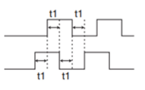 B-phase advances to A by 90°. |
| 1 | Positive direction pulse train + Negative direction pulse train | PULS SIGN | | 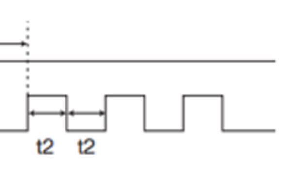 | |
| 3 | pulse train + Signal | PULS SIGN | 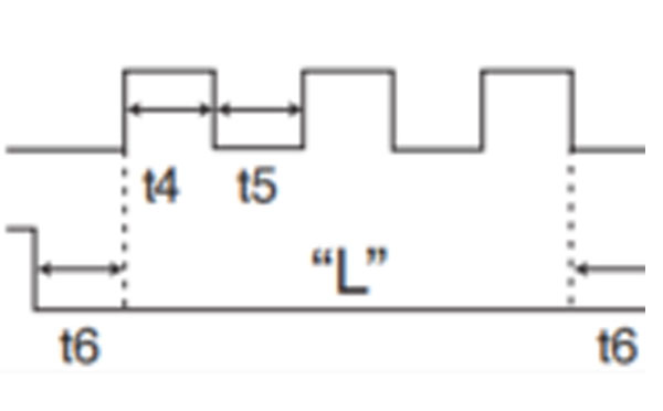 | 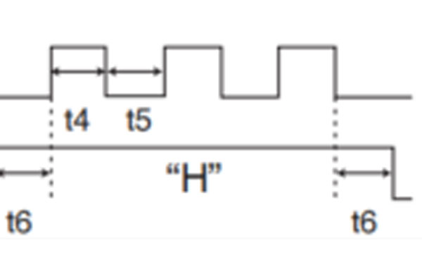 |
| Input I/F of PULS/SIGN signal | Permissible max. input frequency | Min. necessary time width (μs) | ||||||
|---|---|---|---|---|---|---|---|---|
| t1 | t2 | t3 | t4 | t5 | t6 | |||
| Pulse train interface exclusive to line driver PULSH 1, 2, SIGNH1, 2 | A, B-phase Input, multiple of 4 | 8 Mpulse/s | 0.125 | 0.125 | 0.125 | 0.125 | 0.125 | 0.125 |
| Not A, B-phase Input | 4 Mpulse/s | 0.25 | 0.125 | 0.125 | 0.125 | 0.125 | 0.125 | |
| Pulse train interface PULS1, 2, SIGN1, 2 | Line driver interface | 200 kpulse/s | 2 | 1 | 1 | 1 | 1 | 1 |
| Open collector interface | 200 kpulse/s | 5 | 2.5 | 2.5 | 2.5 | 2.5 | 2.5 | |
• P.4-10 "Details of Parameter"
Control signal having the desired function can be applied to any input pin of I/F connector. The logic can be changed.
| Applicable parameter | Default parameter setting(): decimal notation | Default Setup | |||||||||
| Position/Full-closed control | Verocity control | Torque control | |||||||||
| Signal | Logic *1 | Signal | Logic *1 | Signal | Logic *1 | ||||||
| Pin No. | 8 | Title signal | SI1 input | Pr4.00 | 00828282h(8553090) | NOT | Normal Close | NOT | Normal Close | NOT | Normal Close |
| Symbol | SI1 | ||||||||||
| Pin No. | 9 | Title of signal | SI2 input | Pr4.01 | 00818181h(8487297) | POT | Normal Close | POT | Normal Close | POT | Normal Close |
| Symbol | SI2 | ||||||||||
| Pin No. | 26 | Title of signal | SI3 input | Pr4.02 | 0091910Ah(9539850) | VS-SEL1 | Normal Open | ZEROSPD | Normal Close | ZEROSPD | Normal Close |
| Symbol | SI3 | ||||||||||
| Pin No. | 27 | Title of signal | SI4 input | PR4.03 | 00060606h(394758) | GAIN | Normal Open | GAIN | Normal Open | GAIN | Normal Open |
| Symbol | SI4 | ||||||||||
| Pin No. | 28 | Title of signal | SI5 input | Pr4.04 | 0000100Ch(4108) | DIV1 | Normal Open | INTSPD3 | Normal Open | — | — |
| Symbol | SI5 | ||||||||||
| Pin No. | 29 | Title of signal | SI6 input | Pr4.05 | 00030303h(197379) | SRV-ON | Normal Open | SRV-ON | Normal Open | SRV-ON | Normal Open |
| Symbol | SI6 | ||||||||||
| Pin No. | 30 | Title of signal | SI7 input | Pr4.06 | 00000f07h(3847) | CL | Normal Open | INTSPD2 | Normal Open | — | — |
| Symbol | SI7 | ||||||||||
| Pin No. | 31 | Title of signal | SI8 input | Pr4.07 | 00040404h(263172) | A-CLR | Normal Open | A-CLR | Normal Open | A-CLR | Normal Open |
| Symbol | SI8 | ||||||||||
| Pin No. | 32 | Title of signal | SI9 input | Pr4.08 | 00050505h(328965) | C-MODE | Normal Open | C-MODE | Normal Open | C-MODE | Normal Open |
| Symbol | SI9 | ||||||||||
| Pin No. | 33 | Title of signal | SI10 input | Pr4.09 | 00000E88h(3720) | INH | Normal Close | INTSPD1 | Normal Open | — | — |
| Symbol | SI10 | ||||||||||
| • The function depends on parameter setup. Refer to P.4-6 to P.4-85. *1 Operation of Normal Open and Normal Close: P.3-54 • Safety Precautions Usually, please set drive inhibit input (POT, NOT) and forced alarm input (ESTOP) to Normal Close that is used to stop upon disconnection of cable. When setting the drive inhibit input to Normal Open, verify that the setting will not cause safety problem. | |||||||||||
| Title of signal | Servo-ON input | Related control mode | P | S | T | F | ||
| Symbol | SRV-ON | Default assignment | 29 (SI6) | I/F circuit | P.3-33 | |||
| • This signal turns on/off the servo (motor). | ||||||||
| Title of signal | Positive direction over-travel inhibition input | Related control mode | P | S | T | F | ||||
| Symbol | POT | Default assignment | 9(SI2) | I/F circuit | P.3-33 | |||||
| ||||||||||
| Title of signal | Negative direction over-travel inhibition input | Related control mode | P | S | T | F | ||
| Symbol | NOT | Default assignment | 8(SI1) | I/F circuit | P.3-33 | |||
| ||||||||
| Title of signal | Deviation counter clear input | Related control mode | P | S | T | F | |||||||||||||||
| Symbol | CL | Default assignment | 30 (SI7) | I/F circuit | P.3-33 | ||||||||||||||||
<Signal width and clear timing>
*1 Deviation counter clear input ON/OFF = input photocoupler ON/OFF This function can be assigned to only SI7. Allocation of this function to any other pin will cause an error. | |||||||||||||||||||||
• P.4-52, 57 "Details of Parameter"
| Title of signal | Alarm clear input | Related control mode | P | S | T | F | ||
| Symbol | A-CLR | Default assignment | 31 (SI8) | I/F circuit | P.3-33 | |||
When alarm clear input (A-CLR) is kept enabled, all potential alarms and warnings will be prevented. | ||||||||
| Title of signal | Command pulse inhibition input | Related control mode | P | S | T | F | ||
| Symbol | INH | Default assignment | 33 (SI10) | I/F circuit | P.3-33 | |||
This function can be assigned to only SI10. Allocation of this function to any other pin will cause an error. When INH input is ON, the deviation will be caused between the positional command administrated by controller and internal positional command from the filter that receives the positional command from servo drivers, and orginal location before being input INH positional command will be lost. Therefore, it is supposed to reset the original locationwhen it needs to restart return to origin action. | ||||||||
| Title of signal | Control mode switching input | Related control mode | P | S | T | F | ||
| Symbol | C-MODE | Default assignment | 32 (SI9) | P.3-33 | ||||
| • Selects a control mode. • This signal is required in all control modes. No setting will cause an error. | ||||||||
| Title of signal | Electronic gear (division/multiplication) switching input 1 | Related control mode | P | S | T | F | ||||||||||||||||||||||||
| Symbol | DIV1 | Default assignment | 28 (SI5) | I/F circuit | P.3-33 | |||||||||||||||||||||||||
| Title of signal | Electronic gear (division/multiplication) | Related control mode | P | S | T | F | ||||||||||||||||||||||||
| Symbol | DIV2 | Default assignment | — | I/F circuit | P.3-33 | |||||||||||||||||||||||||
| • Up to 4 numberators can be used for command dividing/multiplying by using DIV1 and DIV2. <DIV1 and DIV2 vs numerator/denominator of selected command dividing/multiplying process>
The numerator of command division can be changed by using DIV1 and DIV2 can be switched, the relationship of the positional that send from servo drivers and internal positional command will be change.Therefore, it is supposed to reset the origional location when it needs to restart return to origin action. | ||||||||||||||||||||||||||||||
| Title of signal | Damping control switching input 1 | Related control mode | P | S | T | F | ||
| Symbol | VS-SEL1 | Default assignment | 26(SI3) | I/F circuit | P.3-33 | |||
| Title of signal | Damping control switching input 2 | Related control mode | P | S | T | F | ||
| Symbol | VS-SEL2 | Default assignment | — | I/F circuit | P.3-33 | |||
| • Selects applicable frequency for damping control. Also refer to P.4-25 "Pr2.13 [Damping filter switching selection]" | ||||||||
| Title of signal | Gain switching input | Related control mode | P | S | T | F | ||
| Symbol | GAIN | Default assignment | 27 (SI4) | I/F circuit | P.3-33 | |||
| ||||||||
| Title of signal | Torque limit switching input | Related control mode | P | S | T | F | ||||||||||||||||||||||||||||||||||||||||||||
| Symbol | TL-SEL | Default assignment | — | I/F circuit | P.3-33 | |||||||||||||||||||||||||||||||||||||||||||||
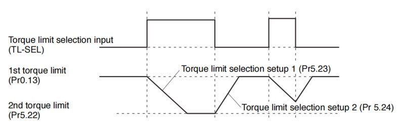 When the 1st torque limit (Pr0.13) and the 2nd torque limit (Pr5.22) are changed from the front panel or through communication, the changing rate setup is ignored and the new torque limit value is immediately and directly applied. That is, changing rate setting is effective only when the selection is made by using the torque limit select input (TL-SEL). | ||||||||||||||||||||||||||||||||||||||||||||||||||
| Title of signal | Selection 1 input of internal command speed | Related control mode | P | S | T | f | ||||||||||||||||||||||||||||||||||||||||||||||||||||||||
| Symbol | INTSPD1 | Default assignment | 33(SI10) | I/F circuit | P.3-33 | |||||||||||||||||||||||||||||||||||||||||||||||||||||||||
| Title of signal | Selection 2 input of internal command speed | Related control mode | P | |||||||||||||||||||||||||||||||||||||||||||||||||||||||||||
| Title of signal | Selection 2 input of internal command speed | Related control mode | P | S | T | F | ||||||||||||||||||||||||||||||||||||||||||||||||||||||||
| Symbol | INTSPD2 | Default assignment | 30 (SI7) | I/F circuit | P.3-33 | |||||||||||||||||||||||||||||||||||||||||||||||||||||||||
| Title of signal | Selection 3 input of internal command speed | Related control mode | P | S | T | F | ||||||||||||||||||||||||||||||||||||||||||||||||||||||||
| Symbol | INTSPD3 | Default assignment | 28 (SI5) | I/F circuit | P.3-33 | |||||||||||||||||||||||||||||||||||||||||||||||||||||||||
Internal command speed switching pattern should be so arranged as shown below that signal input signals are selected alternately. If 2 or more input signals are selected simultaneously, unspecified internal command speed may be advertently selected, whose setting value and acceleration/decelaration setting will cause unexpected operation. 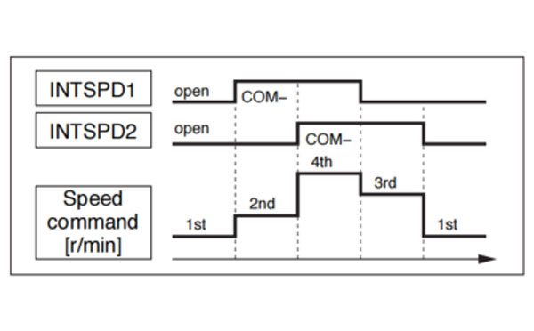 Example 1) When Pr3.00 = 1 or 2 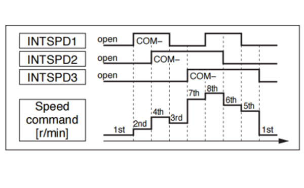 Example 2) When Pr3.00 = 3 | ||||||||||||||||||||||||||||||||||||||||||||||||||||||||||||||
| Title of signal | Speed zero clamp input | Related control mode | P | S | T | F | ||
| Symbol | ZEROSPD | Default assignment | 26 (SI3) | I/F circuit | P.3-33 | |||
| ||||||||
| Title of signal | Speed command sign input | Related control mode | P | S | T | F | ||
| Symbol | VC-SIGN | Default assignment | — | I/F circuit | P.3-33 | |||
| Title of signal | Speed command sign input | Related control mode | P | S | T | F | ||
| Symbol | VC-SIGN | Default assignment | — | I/F circuit | P.3-33 | |||
| ||||||||
| Title of signal | Torque command sign input | Related control mode | P | S | T | F | ||||||
| Symbol | Torque command sign input | Related control mode | P | S | T | F | ||||||
| Symbol | TC-SIGN | Default assignment | — | I/F circuit | P.3-33 | |||||||
| ||||||||||||
| Title of signal | Forced alarm input | Related control mode | P | S | T | F | ||
| Symbol | E-STOP | Defaul assignment | — | I/F circuit | P.3-33 | |||
| ||||||||
| Title of signal | Inertia ratio switching input | Related control mode | P | S | T | F | ||||||||
| Symbol | J-SEL | Default assignment | — | I/F circuit | P.3-33 | |||||||||
| ||||||||||||||
| Title of signal | Dynamic brake (DB) switch input | Related control mode | P | S | T | F | ||
| Symbol | DB-SEL | Default assignment | — | I/F circuit | P.3-33 | |||
| ||||||||
| Pin No. | 14 | Title of signal | AI1 input | Correspondence function |
| Symbol | AI1 | SPR, TRQR, SPL | ||
| Pin No. | 16 | Title of signal | AI2 input | Correspondence function |
| Symbol | AI2 | TRQR, P-ATL | ||
| Pin No. | 18 | Title of signal | AI3 input | Correspondence function |
| Symbol | AI3 | N-ATL |
| Title of signal | Positive direction Torque limit input | Related control mode | P | S | T | F | ||||||||||||||||||||||||||||||||
| Symbol | P-ATL | I/F circuit | P.3-34 | |||||||||||||||||||||||||||||||||||
| Title of signal | Negative direction Torque limit input | Related control mode | P | S | T | F | ||||||||||||||||||||||||||||||||
| Symbol | N-ATL | I/F circuit | P.3-34 | |||||||||||||||||||||||||||||||||||
| • Specify the torque limit for each direction value by the analog voltage.
*1 When specifying the torque limit value through the parameter, refer to P.4-58 "Torque limit select function" | ||||||||||||||||||||||||||||||||||||||
• P.4-6 to P.4-85 "Details of Parameter"
Only for possition control type is not provided with analog input.
Only for the standard type is not provided with analog input.


